|
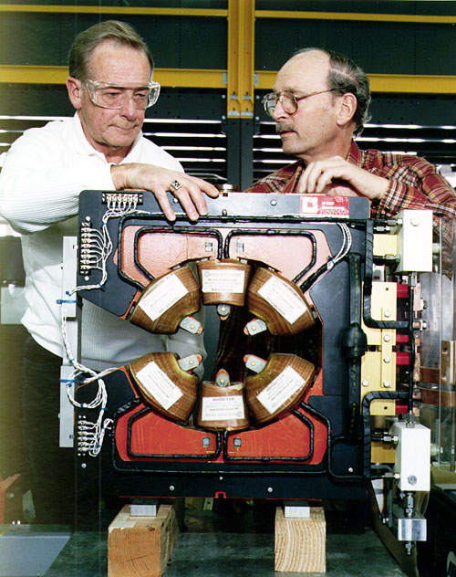
Calculated Details of the Design Parameters for the Storage Ring Vertical/Horizontal Correction Magnets at 7.7 GeV (Horizontal Dipole)
| Number of magnets |
318 |
| Type of magnet |
Dipole HF |
| Type of excitation |
DC |
| Dipole field strength |
0.1686 T |
DESIGN AND OPERATING PARAMETERS OF A SINGLE MAGNET:
| Gap |
|
|
|
| |
Gap axis shape |
Straight |
|
| |
Effective length of field along gap axis |
16.7 |
cm |
| |
Total width of pole |
5.39 |
cm |
| |
Total gap height |
8.49 |
cm |
| Core |
|
|
|
| |
Distance from - Field edge to - Core end |
4.83 |
cm |
| |
Overall core - Length (Magnetic steel ONLY) |
7.01 |
cm |
|
Coil
|
|
|
|
| |
Conductor material |
Copper |
|
| |
Conductor - Height |
.467 |
cm |
| |
- Width |
.419 |
cm |
| |
- Hole diameter |
.241 |
cm |
| |
- Corner radius |
.08 |
cm |
| |
Conductor min. bend radius (inside edge) |
|
|
| |
- Width |
2.4 |
cm |
| |
Insulation - Tape - Thickness - Turn |
.0095 |
cm |
| |
- Ground |
.038 |
cm |
| |
- Width - Turn |
2.5 |
cm |
| |
- Ground |
2.5 |
cm |
| |
Insulation total thickness - Turn |
.019 |
cm |
| |
- Ground |
.107 |
cm |
| |
Allowance between layers of conductor |
.025 |
cm |
| |
Allowance between rows of conductor |
.025 |
cm |
| |
Aberage turn length |
38.5 |
cm |
| |
Ampere-turns per pole |
14822 |
At |
| |
Number of layers of conductors per pole |
36 |
|
| |
Number of conductor per layer per pole |
4 |
|
| |
Effective number of turns per magnet |
240 |
|
| |
Number of turns per cooling circuit |
60 |
|
| |
Number parallel connected conductors per magnet |
1 |
|
|
Electrical
|
|
|
|
| |
Stored energy |
58.2 |
J |
| |
Total inductance |
7.6 |
mH |
| |
Total coil resistance |
118 |
mOhms |
| |
Supply current |
124 |
A |
| |
Voltage across magnet |
14.6 |
V |
| |
Overall magnet - Length |
14.15 |
cm |
OPERATING PARAMETERS OF THE MAGNET SYSTEM:
| Cooling circuit |
|
|
| Coolant supply temperature |
32 |
°C |
| Coolant temperature gradient |
13.0 |
°C |
| Pressure gradient |
80 |
psi |
| Coolant flow |
168 |
gpm |
| Power losses |
|
|
| Electrical losses in magnets |
572 |
kW |
| Electrical pwer to operate coolant pumps |
8.3 |
kW |
SOME AUXILIARY PARAMETERS FOR THIS DESIGN ARE:
| Cross-sectional area of conductor |
.145 |
cm2 |
| Current density in conductor |
851 |
A/cm2 |
| Current density in coil |
435 |
A/cm2 |
| Reynold's number |
6423 |
|
| Coolant flow velocity |
182 |
cm/s |
| Maximum conductor temperature |
45.2 |
°C |
|
