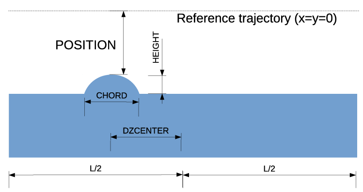
Simulates a semi-circular protuberance from one or both walls of the chamber.
Parallel capable? : yes
GPU capable? : no
Back-tracking capable? : no
| Parameter Name | Units | Type | Default | Description |
| L | M | double | 0.0 | insertion length |
| CHORD | M | double | 0.0 | z length of speed bump |
| DZCENTER | M | double | 0.0 | z center displacement of speed bump relative to middle of object |
| HEIGHT | M | double | 0.0 | height above the surrounding chamber |
| POSITION | M | double | 0.0 | position of peak relative to ideal trajectory |
| DX | M | double | 0.0 | horizontal misalignment |
| DY | M | double | 0.0 | vertical misalignment |
| INSERT_FROM | STRING | NULL | direction from which inserted (x, +x, -x, y, +y, -y) |
|
| SCRAPER_CONVENTION | short | 0 | Historically, the interpretation of the POSITION parameter was dependent on the insertion direction. Set this to 1 to make it consistent with the SCRAPER element. |
|
| GROUP | string | NULL | Optionally used to assign an element to a group, with a user-defined name. Group names will appear in the parameter output file in the column ElementGroup |
|
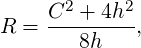
This element simulates a commonplace type of aperture restriction, consisting of a bump on one or both sides of a chamber. The parameters of the speedbump are illustrated in Fig. 4 It may be useful to know that the radius R of the cylinder from which the speedbump is made is
|
| (163) |
where C is the chord length and h is the bump height. Solving for h, we have
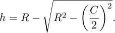 | (164) |
SREFFECTS